In cranes featuring cable and pulley hoisting systems, the hook block is the structural element responsible for connecting the load to the crane. This is most commonly achieved through standardized hooks or, less frequently, via pins.
They are essentially composed of structural plates, tie rods, sheaves, axles, the hook (or pin), a lifting eye, and counterweight plates. Blocks without sheaves, which connect to only a single part of the crane’s line, are popularly known as “headache balls” or simply “balls.”
Generally, each crane model has specific types of hook blocks defined by the manufacturer based on hoisting capacity. The number of sheaves, the number of rope falls, and friction losses will directly affect its load capacity.
Thus, four factors affect the Hook Block Working Load (WLL): 1) winch line pull; 2) number of parts of line (rope falls); 3) friction in the sheave bearings; 4) winch position and the number of equalizer sheaves.
Although top crane manufacturers include the WLL for all hook block variations in their manuals, others do not provide this information, potentially requiring analytical calculation. Figure 1 shows the layout of the winch, sheaves, and a hook block with 4 parts of line. This configuration, with the winch below the boom sheaves, is called “Case 1.” “Case 2” (winch at or above sheave level) and “Case 3” (two winches with an equalizer sheave) will not be covered here but can be accessed at www.techcon.eng.br.

The Hook Block Working Load Limit (WLL) for “Case 1” is calculated using the following equation:
WLL = SG · N ·
Where:
K is the factor to consider friction.
N is the number of wire rope falls.
SG is the winch workload, informed by the crane manufacturer.
The K factor is the ratio of the rope tension exiting the sheave to the rope entering the sheave, and it depends on the quality of the support used in the sheave. Crosby and Gunnebo specify K = 1.02 for blocks with roller bearings and K = 1.045 for blocks or snatch blocks with bronze bushings. Liebherr blocks generally have a value of K = 1.0155.
In the CTM equation, the SG factor can be removed, obtaining the system efficiency as a function of the “N” rope falls, EN, allowing the assembly of a table independent of the winch capacity:
EN = N ·
Practical applications
1 · Create a table with the efficiency of Crosby blocks for roller bearings and bronze bushings, with up to six rope falls.
Solution:
The quantity N of falls is varied for roller bearings (R) with K = 1.02 and for bronze bushings (B) with K = 1.045:
E1,R = 1 · ≅ 0,98
E1,B = 1 · ≅ 0,96
E2,R = 2 · ≅ 1,94
E2,B = 2 · ≅ 1,87
Calculating for the remaining values of N, the efficiency table can be assembled:
| Number of rope falls N | Block Efficiency | |
| Roller bearing EN,R | Bronze bushing EN,B | |
| 1 | 0,98 | 0,96 |
| 2 | 1,94 | 1,87 |
| 3 | 2,88 | 2,75 |
| 4 | 3,81 | 3,59 |
| 5 | 4,71 | 4,39 |
| 6 | 5,60 | 5,16 |
2 · A winch set with an SG of 7.6 tons and a Gunnebo block with a WLL (Working Load Limit) of 70 tons, featuring 4 sheaves with roller bearings, is configured with 5 rope falls. Calculate the Block Working Load (BWL).
Solution:
Since the efficiency for 5 falls is already tabulated, simply multiply it by SG, while ensuring it meets the WLL (Working Load Limit) of the block.
WLL5 = SG · E5,R = 7,6 · 4,71 = 35,8 t
WLL5 ≤ WLL ∴ 35,8 < 70 t
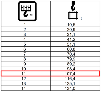
3 · A Liebherr LTM 1200 5.1 crane is configured with a block with a WLL (Working Load Limit) of 108 tons, featuring 5 sheaves with roller bearings. The manufacturer’s catalog states that the SG is 105 kN. What is the BWL for the maximum number of rope falls possible?
Solution:
The maximum number of rope falls is 2*S + 1, where S is the number of sheaves in the block. Since the block has 5 sheaves, the value of N is 11.
The SG unit is in kN (kilonewtons), whose value in tons-force is 10.7 tf (105 / 9.81), being the same value for the corresponding mass, resulting in SG = 10.7 t.
Applying the formula:
WLL11 = SG · N · = 10,7 · 11 · ≅ 107,4 t
WLL11 ≤ WLL ∴ 107,4 < 108 t
The value found is the same as the one provided by the block configuration table, found in the crane’s load chart manual (Figure 2).
Final considerations
- Block Working Load (BWL): In all cases, the BWL must be less than or equal to the block’s Working Load Limit (WLL) specified by the manufacturer.
- BWL vs. GRC: The BWL must always be greater than or equal to the Gross Required Capacity (GRC).
- BWL vs. GTC: It is a recommended practice that the BWL be greater than the crane’s Gross Tabulated Capacity (GTC).
- Sheave Tension: Verify if the block weight is sufficient to maintain proper wire rope tension for winding on the drum, as per the crane’s operating manual.
- Wire Rope Specs: Always use wire ropes with the diameters and types specified by the manufacturer.
The full article can be read in Crane Brasil magazine, issue no. 103.